
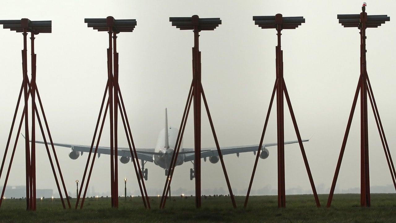
The fog is so thick that the crew of an airliner on final approach cannot see the ground, let alone the runway. Yet the jet is tracking a line through the murk with an accuracy measured in metres, descending along an invisible slope towards a touchdown point it will not see until the last moment, if at all.
What holds it there is a pair of radio signals from antennas standing in the grass beside the runway. The Instrument Landing System, ILS for short, has been the world’s standard precision approach aid since the years after the Second World War, and it still brings in a huge share of the airliners that land in bad weather today.
It is also a lovely piece of engineering. The trick is not a narrow beam pointed at the runway, as most diagrams suggest. It is two audio tones and a needle that compares them.
Datos rápidos
- Qué es: A ground-based radio aid that gives aircraft precise lateral and vertical guidance to a runway in bad weather
- Localizer: Left-right guidance; 40 channels between 108.10 and 111.95 MHz; antenna array beyond the far end of the runway
- Glideslope: Up-down guidance; UHF, 329.15 to 335.00 MHz; path normally 3 degrees; antenna beside the runway
- Cómo funciona: Compares the depth of modulation of a 90 Hz and a 150 Hz tone; equal means on course
- Range information: 75 MHz marker beacons or, increasingly, DME
- CAT I: Decision height 200 ft, RVR 2,400 ft (1,800 ft with touchdown zone and centreline lights)
- CAT II / III: CAT II: 100 ft and RVR 1,200 ft; CAT III down to no decision height, CAT IIIc with no RVR limit
- Orígenes: Doolittle’s instrument-only flight, 24 September 1929; adopted as the ICAO standard after the Second World War
- Sucesor: Satellite approaches: LPV and GBAS, which can serve up to 48 approaches from one station
Two beams, two jobs
An ILS has two independent halves. The localizer gives left-right guidance along the extended runway centreline. Its antenna array stands beyond the far end of the runway, so an approaching aircraft flies straight towards it. According to the FAA’s Aeronautical Information Manual, the localizer transmits on one of 40 ILS channels between 108.10 and 111.95 MHz, and its course is adjusted to be 700 feet wide, full fly-left to full fly-right, at the runway threshold.
El glideslope gives up-down guidance. It is a separate UHF transmitter between 329.15 and 335.00 MHz, placed 750 to 1,250 feet down the runway from the threshold and offset 250 to 650 feet to the side. Its beam is 1.4 degrees thick vertically, and its path is normally set at 3 degrees above the horizontal. That angle puts an aircraft on the slope about 200 feet above the runway when it is roughly 3,500 feet from the threshold.
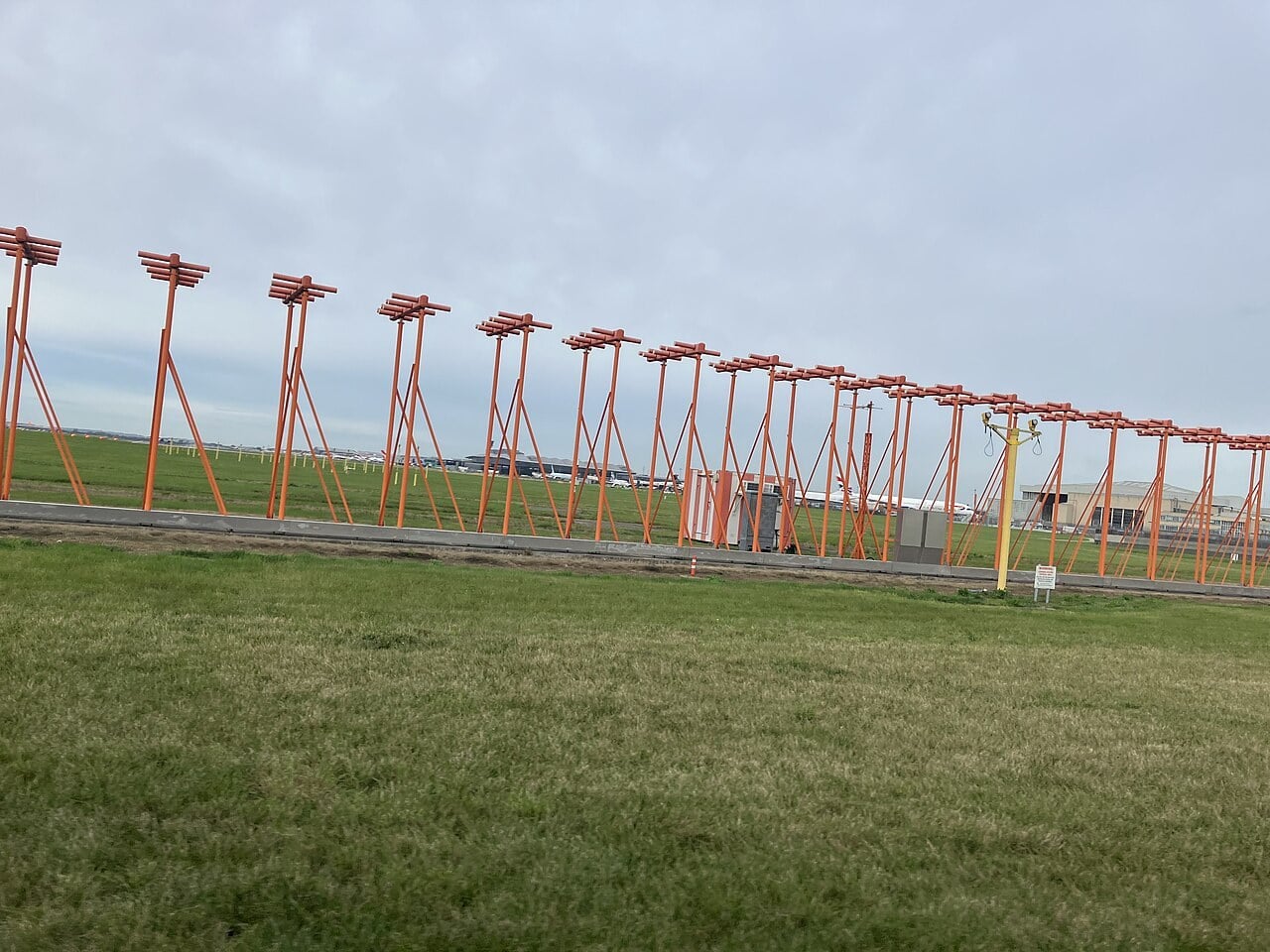
The two frequencies come in fixed pairs set by ICAO. Tune the localizer, and the receiver automatically picks the matching glideslope: localizer 109.30 MHz, for example, always goes with glideslope 332.00 MHz. The localizer also transmits a Morse identifier that always begins with the letter I, two dots, so the crew can confirm which runway’s ILS they have tuned. The glideslope transmits no identifier of its own.
The 90 and 150 Hz trick
Here is the clever part. Both the localizer and the glideslope carry two audio tones riding on the radio carrier, one at 90 Hz and one at 150 Hz. The antennas shape the signal so that, on the localizer, the 90 Hz tone dominates on one side of the centreline and the 150 Hz tone on the other. On the glideslope, Australia’s Civil Aviation Safety Authority explains, 150 Hz predominates below the glide path and 90 Hz above it.
Both tones are radiated across the whole pattern. What changes with position is the difference in depth of modulation, how strongly each tone is impressed on the carrier. The receiver measures the two, subtracts one from the other and drives a needle. Exactly on the centreline the difference is zero and the needle sits in the middle.
Rohde & Schwarz’s explainer on how the Instrument Landing System guides an aircraft to the runway.
The beauty is that the measurement does not depend on signal strength. Static, fading or the signal growing stronger as the aircraft closes on the runway affect both tones equally, so the needle stays honest. Monitors on the ground watch the transmissions continuously, and if the signal drifts outside tight limits the station shuts down or strips its guidance, which raises a warning flag in the cockpit rather than showing a false course.
From vibrating reeds to a world standard
The idea is older than the airliner. On 24 September 1929, at Mitchel Field on Long Island, Lieutenant Jimmy Doolittle took off, flew a set course and landed a Consolidated NY-2 biplane by instruments alone, his cockpit sealed under a hood. His instruments included a Sperry artificial horizon and directional gyro, a Kollsman altimeter and a radio course indicator built from two vibrating reeds.
Through the 1930s competing beam systems spread, including the German Lorenz beam. During the Second World War the US Army Air Forces fielded a portable ILS, the SCS-51, with a straight glide path on higher frequencies that were less affected by the ground. After the war it was available, cheap to build and free of secrets, and the newly formed International Civil Aviation Organization adopted ILS as the international standard precision approach system. Its specification still sits in Annex 10 to the Chicago Convention.
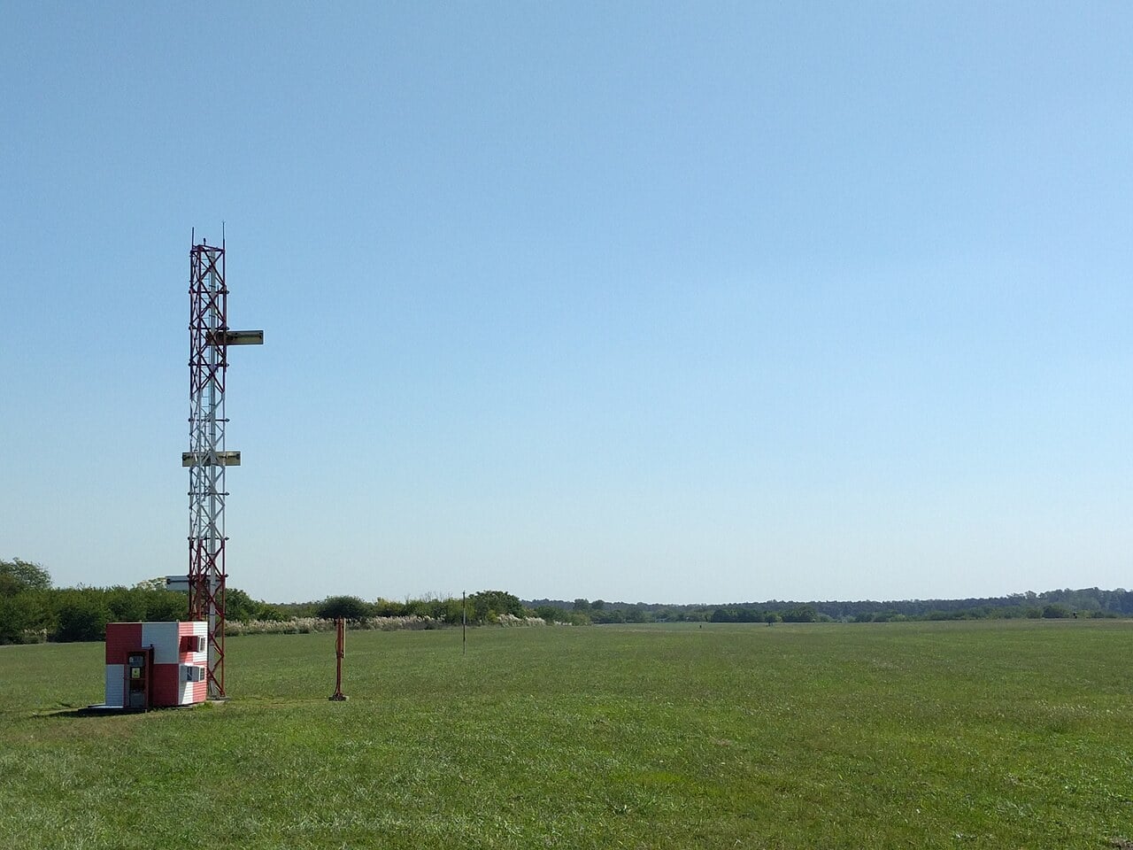
Along the approach, the crew needs to know not just which way to steer but how far they have to go. That is the job of the range information. Classic installations used marker beacons, low-power 75 MHz transmitters that flash a light and sound a tone as the aircraft passes overhead: blue for the outer marker, amber for the middle and white for the inner. Today distance measuring equipment, DME, is increasingly used instead, and the FAA no longer installs middle markers at new ILS sites.
Decision height and the categories
An ILS does not land the aircraft by itself. It brings it to a decision height, the point where the pilots must see the approach lights or runway, or go around. How low that point can be is what the ILS categories define. The FAA’s lowest authorized minimums are:
CAT I: decision height 200 feet, runway visual range (RVR) 2,400 feet, or 1,800 feet with touchdown zone and centreline lighting.
CAT II: decision height 100 feet, RVR 1,200 feet.
CAT IIIa: no decision height or one below 100 feet, RVR not less than 700 feet.
CAT IIIb: no decision height or one below 50 feet, RVR below 700 but not less than 150 feet.
CAT IIIc: no decision height and no RVR limit.
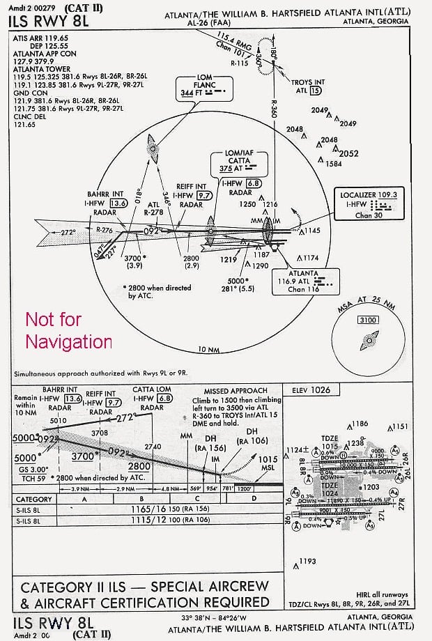
CAT II and III need special aircraft equipment, crew training and authorisation, and the airport has to protect the ILS “critical areas” around the antennas, because a taxiing aircraft or vehicle in the wrong place can bend the beam. In CAT III weather there is too little to see for a manual landing, so the approach ends in an automatic landing or a pilot flying head-up display guidance. The breakthrough came in Britain: on 10 June 1965 a BEA Hawker Siddeley Trident made the first automatic landing by a civil airliner in scheduled passenger service.
Cockpit view of an A330neo flying an automatic landing in low visibility at Frankfurt (AeroNewsGermany, in German).
For fog-prone airports, those categories decide whether flights operate at all. When dense winter fog settles over Delhi, the airport keeps landing aircraft on its CAT III systems while flights that are not equipped and crewed for them are delayed or diverted.
Why satellites are coming for it
ILS has two weaknesses: cost and rigidity. Every runway end needs its own localizer, glideslope and frequency pair, the antennas need careful siting and regular flight inspection, and the beam supports only a straight-in approach at a single fixed angle.
Satellite navigation offers an alternative. In the United States, WAAS-based LPV approaches give ILS-like vertical guidance without any equipment at the runway, and the FAA now publishes more LPV approaches than CAT I ILS procedures. For the lowest minimums, the answer is the Ground Based Augmentation System, GBAS. Reference receivers at surveyed points on the airport calculate GPS errors and broadcast corrections over a VHF data link twice every second. According to the FAA, one facility can provide up to 48 approaches, where an ILS serves a single runway end, and new GBAS standards are designed to take it to CAT III minima.
The catch is that satellite signals are faint. Jamming and spoofing have made pilots and regulators wary of switching off the ground-based system too quickly, and in 2026 Switzerland paused the planned removal of the ILS at Bern after Europe’s aviation safety regulator began advising states to keep ILS available for emergencies, as Afterburner reported in September.
So the old antennas in the grass are not going anywhere just yet. Nearly a century after Doolittle watched two reeds vibrate in a hooded cockpit, the principle is unchanged: compare two signals, centre the needle, and trust it all the way down to the decision height.
Sources: FAA Aeronautical Information Manual (chapter 1, section 1-1-9, Instrument Landing System); FAA, Ground Based Augmentation System: How It Works; Civil Aviation Safety Authority (Australia), Operational Notes on the Instrument Landing System; Air & Space Forces Magazine, “Flying Blind”; IEEE Milestone, First Blind Takeoff, Flight and Landing, 1929; DT Next; Wikipedia (Instrument landing system; Autoland; Hawker Siddeley Trident; Jimmy Doolittle)


0 Comments